
Fyling Officer Ted Kosh, No. 3 Squadron, RAF
 Flying Officer Ted Kosh was killed in July 1944 when his Hawker Tempest crashed into the ground near Rye in East Sussex during a sortie to intercept V1 bombs targeted on London. P/O Kosh was a young, relatively inexperienced pilot and as a member of No.3 Squadron in the summer of 1944 his mission was to try and shoot down or tip as many V1s as possible.
The oldest of RAF squadrons, No 3 Squadron, Royal Flying Corps, was formed at Larkhill on 13 May 1912 from No 2 (Aeroplane) Company. At the outbreak of war in 1939 it was equipped with Hurricanes at Biggin Hill. A brief stint as part of the BEF in France was followed by relocation to Scotland on night-patrol duties. During 1943, the Squadron replaced the Hurricanes with Typhoons and switched to the anti-shipping and intruder roles. A switch to Tempests in 1944 saw No 3 Sqn destroy 288 V1 flying bombs.
While it wasn’t a very glamorous job, taking on the V1’s pounding southern England almost every day was still very dangerous. Tipping could damage the wing and shooting down a flying bomb could result in a very hazardous situation indeed for the shooter. Below are some stills taken from gun camera footage of a V1 “kill”.


Remarkably, there is video of P/O Kosh’s Tempest taxiing for a mission, his aircraft JF-K is the second of the two Tempests taxiing past the camera. This is a still from the movie and while it’s admitedly difficult to make out the “K”, it is clear in the original. It’s possible this is a different JF-K, and even it is, that Ted was not piloting it here, but I like to think it is.

The cause of Ted’s crash wasn’t known and has not been recorded but it seems quite likely an exploding V1 may have been the cause – certainly his aircraft was described as “crashed in flames” and other explanations seem less plausible.
Ted had three credited victories at the time of his death. Ted’s family buried him at Hawkinge cemetery in Kent.
In 1995 P/O Kosh’s crash site was excavated. It’s reported (but seems strange to me) that most of P/O Kosh’s remains were still in his crashed Tempest. He was finally removed from it and buried with full honours.
Hawker Tempest V Development

The Hawker Typhoon was the result of Hawker’s Chief Designer, Sydney Camm’s team’s work on specification F.18/37 as early as 1937 for a totally new fighter (from the Hurricane). Initially it was to have a 1491-kW (2000hp) engine, either a Rolls-Royce Vulture or Napier Sabre. As events played out, the Vulture-engined Typhoon (as that variant became known as) was unsuccessful but the Sabre engined Typhoon eventually became a great low-level fighter/bomber.
The Typhoon’s short comings were its performance at altitude, manifesting with engine problems and a wing prone to shock stalling and flow breakaway at even modest speeds. The engine problem was possibly solved with the potential of the Bristol Centaurus already tested in a Tornado prototype HG641. In March 1940 Camm authorized work on a new wing with reduced thickness/chord ratio and a later aerofoil profile of a type called “laminar”, with a maximum thickness much further aft than before.
The new wing would house four 20mm cannon as opposed to the Typhoon’s machine guns, and as these were installed farther back than in the Typhoon MkIB with the breaches and magazines behind the rear spar, a large chord was necessary at this point. Sydney Camm later said “The Air Staff wouldn’t buy anything that didn’t look like a Spitfire,” whether he was joking or not, the new wing took on a decidedly elliptical shape reminiscent of the Supermarine product. The wing ended up, after the tips were clipped, with a shorter span than the Typhoon but with a larger surface area.
A key and innovative feature of the wing was use of integral radiator in the leading edge for the Sabre engine. However, combined with the thinner wing this seriously reduced fuel capacity and to solve the problem the fuselage was lengthened by 21 inches ahead of the cockpit. The added length to the fuselage meant the vertical tail had to be enlarged. The design was virtually complete by October 1941, specification F.10/41 was written around it, and on November 18 a contract was placed for two prototypes, HM595 and HM599. Originally known as the Typhoon MkII, the new aircraft was officially dubbed Tempest in January 1942 and the contract extended to five more prototypes. At this point the program was thus:
LA594 – The [now] cancelled Typhoon MkII (Centaurus engine)
HM595 – Tempest MkV (Sabre engine in Typhoon type installation
HM599 – Tempest MkI (Sabre IV engine and wing radiators)
LA602 & 607 – Tempest MkII (Centaurus engine)
LA610 & 614 – Tempest MkIII or IV (Respectively Griffon IIB or 61 engines)
In the event however, LA594 was never built and LA610 and 614 were diverted to a later program. HM599 should have been the first but the continued work required on the new engine/radiator installation prompted Camm to push through HM595 as virtually a Typhoon (including the “car door” cockpit) with the new wing and as such it first flew on September 2, 1942.
A month before this Hawker had received a contract for 400 Tempest MkIs. Hawker test pilots all felt HM595 to be a great improvement over the Typhoon and as soon as possible a bubble canopy was fitted, tailplane chord increased, and a dorsal fillet added. With such a promising start, the first test flight of the “real” Tempest MkI HM599 with the Sabre IV engine and leading-edge radiators was eagerly anticipated by everyone at Hawker. That wait was to last until 24 February 1943 due to engine delays. HM599 flew as basically a modified Typhoon but performed very well, becoming the fastest Hawker fighter to date with a speed of 466mph. Camm forced through production of the new wing at Langley but the Sabre IV continued to be unavailable and as a last resort Camm produced a “productionised” Tempest V based on HM595 but with a properly designed tail. Production of Tempest MkVs on the contract initially issued for 400 Tempest MkIs began in June 1943, with the first coming off the lines on June 21. Ironically, in the same way the RAF got the Spitfire MkIX as the result of an improvisation (Merlin 61 engine in an Spit MkV) instead of the definitive Spitfire MkVIII, they got the Tempest MkV instead of the MkI.
The first 100 produced were armed with the Hispano MkII cannon and were called Tempest MkV Series 1; subsequent production introduced the short barreled MkV cannon with the muzzles inside the leading edge. More important to the pilot was the addition of spring tabs to the ailerons, a first on RAF aircraft, giving all the roll power the pilot needed.
Altogether 800 MkV Tempests were delivered, entering service with the Newchurch Wing (Nos 3, 486 and 56 Sqns) led by Wing Commander R.P.Beamont. This wing, in which Ted Kosh served, proved the most successful of all units operating against V-1 flying bombs, destroying 638 of the RAF’s total of 1,771.


Eduard 1/48 Tempest V c/w Jaguar Correction Set

The Kit
 Eduard have recently announced a new-tool Tempest kit. Included in that are the markings for P/O Ted Kosh’s Tempest MkV. The new kit has, so far, received positive reviews. However, this article is built around the original kit which was somewhat flawed, and therefore includes use of the fuselage correction kit and cockpit detail set produced by Jaguar.
This was my first Eduard kit and I was very pleasantly surprised with the quality of moulding. The kit comprises 62 parts on four sprues with the canopy on a separately packed clear piece. The decals were slightly off register, so slightly that I didn’t notice until I applied them but appeared to be nicely printed and offered two different aircraft. The instruction sheet is clear, using exploded diagrams of the assembly with no text. I used a Jaguar Detail Set on this project. Upon opening up the box I found the cream coloured resin, crisply moulded with very little flash and the pour blocks in easy to remove places. The various pieces were very detailed and seemed consistent with my references. The instructions seemed logical and were clear on placement etc., though I did run into a couple of conundrums, more on this later.
Construction

I followed the Jaguar instructions and started with the fuselage inserts. The instructions will have you cut the fuselage pieces at the rear of the wing insert. When I offered the pieces up to the uncut fuselage pieces it looked to me that they would be too small, with a noticeable step or gap depending on which way I chose to compensate for the lack of circumference. I moved the piece down the fuselage until it reached a spot where it matched the kit piece and decided to cut there. This place happened to be exactly at the point where the canopy rail ends. Having measured twice, I cut both fuselage halves at the same point and then glued the Jaguar resin in with CA glue. Later, I went back and reinforced this joint with epoxy. There was a large gap created where the offset for the designed location at the wing insert differed from where I put it. I filled this gap with some styrene strip and cleaned up with putty.


Next, I removed the kit rudder and cleaned up the edge, being careful to bevel the inside edge to receive the resin rudder later in construction. With this prep work done, it was time to turn my attention to the cockpit itself.
I began by painting all the components matt black. I used Gunze acrylic in this case. When that was dry, I started to remove the major pieces and begin to detail paint them. In retrospect, I could have left them on their cast blocks for this stage, but it makes little difference with the larger pieces. When I was reasonably happy with the finish, I began to add the various other components, black boxes and levers from both the photo-etch and the resin parts.
After this laborious process was nearly complete, with the photo-etch mostly attached I dry brushed with dark grey and highlighted with silver pencil. Next, I began work on the instrument panel which was, for me, the highlight of the entire detail set. As instructed, I painted the back side of the acetate instrument sheet with a cream colour and then glued it to the panel piece. Next, I cut out the photo-etch covers and glued them over the acetate, being very careful to align it all correctly. This whole process took no more than 30 minutes and achieved a very satisfactory result.


Next, I assembled the right side, rear bulkhead, firewall and floor pieces, using CA to join them. At about this time, I though it all looked a little bland so I detail painted some more, applied a wash and used a little more colour to “busy up” the look. I was working from photos and was careful to use appropriate colours. When I was happy with how they all looked, it was time to begin fitting the pieces in the fuselage halves.
With hindsight, I should have put the instrument panel in first and used it as the datum point for the rest of the cockpit pieces. As it was, I didn’t and so made all kinds of extra work for myself, you have been warned!
I started with the left side panel and promptly glued it in the wrong place (as it turned out). With the side panel in place, I glued in some stringers and picked them out with interior green. These stringers are important as they provide the locations for some additional resin and photo-etch pieces. You would think I’d have offered up the instrument panel before now, to check fit but I hadn’t and when I eventually did so, I realized the side panel was about 1.5mm too high. I very carefully prized it up and was able to reposition it without breaking it, after having installed the instrument panel! However, I wasn’t able to move the stringers without really messing up the side, so they had to remain, now a little short. Fortunately, it’s very difficult to see when fuselage is closed up – more on that later too. On the opposite side, I glued in the cockpit assembly, now with the seat and control column attached, this time checking all the time that I had it at the right height. With the cockpit finished and in place, I finally turned my attention to the chin intake pieces in preparation for closing the fuselage.
The pieces in my set for the air intake had some slight casting flaws. Some of the detail in the grill was missing leaving the surface finish flat. That caused a couple of issues when I washed the grill as the wash wouldn’t take and left a spotty coverage. The last thing to do before joining the fuselage, and I nearly forgot to do it, was to insert the very finely moulded exhaust stacks which are a huge improvement over the kit pieces.
As a so-called short run kit, the kit has thicker than average attachment points and no locating pins. During the installation of the cockpit pieces I’d test fitted the fuselage halves many times, so without much ado, I joined the halves with liquid glue, ensuring I nailed the alignment. With this accomplished, the rest of the basic construction went smoothly. I thinned down the trailing edges of the wings and tailplanes before joining them and when dry and cleaned up, I attached them to the fuselage. I needed some filler around the wing and tailplane roots, and quite a lot on the underside where the wing joined the fuselage at the junction of the fuselage insert. All this was relatively easy to clean up. After looking at some references, I saw that there is a decking on the fuselage spine behind the pilot’s headrest. I fashioned a piece with .010 styrene sheet and also replaced the canopy rail which had been damaged during the seam clean up.

The rudder was next, having already removed the kit rudder, I used CA glue to attach the resin replacement, and a great improvement it made too. My final task before painting was to cut the canopy and then attach the pieces. The kit piece is a one complete canopy and windshield. I scored the join on the moulding repeatedly with the back of a #11 blade until the pieces separated and then cleaned up with some 1000 grit paper. I masked with a combination of Tamiya tape and Parafilm. I attached the windshield with white glue and temporarily fixed the canopy with some blue tack.
Painting
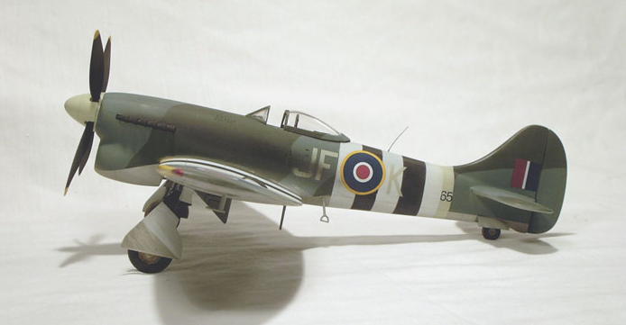
 Tempests were painted in the standard RAF scheme of Dark Green and Ocean Grey over Medium Sea-Grey. Pictures indicate the demarcations were all hard edged. I used Gunze acrylic for the underside and when dry I masked off the MSG with tape and sprayed the Ocean Gray, this time with MM enamel. After letting that dry for a couple of days, I masked the camouflage pattern with tape and sprayed the Dark Green, also with enamel. I was pleased with the resulting edges as they looked to me to be an accurate representation of the real thing.
Next was the D-Day stripes. There is some debate about what the stripes would have looked like soon after D-Day, which is the time this model represents. The stripes were for the most part applied in haste on the night of June 5, often with brushes, mops, and any other implement that may have come to hand. I doubt if they were all exactly 18′ wide and perfectly square and parallel. Below are a couple of contemporary photos to illustrate my case.


Both pictures show unequal sizing and rough application. I chose to try and represent this by masking the stripes by eye without measuring. I felt the edges would still be hard in scale, so I used tape to mask but allowed the dimensions to wander a little. I masked off the white areas first and used MM acrylic white. I sprayed to get about a 95% coverage with just a hint of the underlying camouflage visible, again as I felt this would be accurate. When that was dry, I used Tamiya masking tape to mask off the white and then sprayed the black with the minimum of coverage. When all was dry, I removed the masking and surveyed the result.
Satisfied with the paint work and when it was all fully cured, I used Future for the gloss coat as I suspected my decaling problems on recent models were due to using Metalizer Sealer as the gloss coat. I let the Future dry fully – in this case a trip out of town meant the Future was six days old when I next touched the model and began decaling.
Decals

I was able to use almost all the kit decals except for the K of the code and the couple of digits visible of the serial number. The kit decals went down very well and using the Micro Sol/Set system I had no problems at all. The “K” I got from a spare sheet for another RAF subject and I used some Tally-Ho serial numbers from a generic sheet. This last application confirmed my suspicions regarding the Metalizer Sealer as these same decals had given me huge problem on the last kit I used them on which was sealed with the sealer and not Future. With the decaling complete, I sealed it all up with another coat of Future and set it aside to dry.
Final Assembly and Weathering

Weathering consisted of a dark grey wash and some light pastel work. I haven’t seen very many pictures of these aircraft looking too worn so I didn’t overdo the weathering. I then added the undercarriage, including the resin tail wheel which appears too short to me. With the addition of all the other small items and the propeller, the kit was complete.

References
The Hawker Tempest Page
Christer Landberg’s site, simply the only Tempest site you’ll ever need. My sincere thanks to Christer for (originally) allowing me to use some images from his site as well as the stills that came from movies over there too; I have used that permission for this re-post of the article. I urge you to visit if you have any interest in Tempests or good web sites.
Royal Airforce Cottesmore
Home page of No 3 Sqn from where information on the squadron’s history came.
“Fighters of World War Two” – Edited by David Donald, published by Grange Books. ISBN: 1-84013-150-0
“History of the RAF” – Written by Chaz Bowyer
Copyright
Except where noted otherwise, I sourced all images and photos from the internet and are all used under fair-use. This site does not and will not monetise any of its content. This piece was written and first published in around 2004 and my original notes indicate the above as the sources and permissions granted; I will be happy to add more or adjust as they become apparent or as requested.
I sincerely do not remember where the original source of the information on P/O Ted Kosh. I suspect like most of my Feature Article subjects, I came across it in some random internet search and went from there. In the original piece there was discussion on the circumstances surrounding the excavation of the crash site in 1995. I left it out of this version for reasons of clarity and taste.
As usual, I make no claim of original work in this article except for the photos of the models and text describing their construction and painting.
Any copyrighted material will be removed or credited forthwith upon request by its owner.


Leave a comment